Термостат и реле времени на базе чипа esp8 2 6 6
version: 0.3 (beta) 24.01.2019
Данная прошивка подойдет под любое устройство на базе чипа esp8266, так же и для универсальных устройств на базе данного чипа, например, nodemcu. Надо учитывать, что запрограммированный функционал предусматривает определенное использование выходов чипа esp8266. Рассмотрим работу данной прошивки на примере двух плат NodeMCU v3 и MP3509 от MasterKit.
Основные функции программы это: термостат, реле времени, счетчик импульсов или измерение скорости ( 2 канала ), управление нагрузкой ( 2 реле ), измерение температуры
до 8-ми датчиков на один канал по шине 1-wire ( все датчики подключаются параллельно через резистор 4.7 кОм к выводам data и к питанию 5 Вольт,
резистор подключается как можно ближе к плате устройства, длина провода не может быть большой,
т.к. на устройстве нет схемы формирования шины 1-wire. Смотрите описание команд ow_scan и ow_show. )
и измерение входного напряжения в пределах 1 Вольта
(Измеряемое напряжение, например, уровень заряда аккумулятора 12 вольт, необходимо подать через делитель!) программа, позволяет ввести коэффициент пересчета и выводить
уже реальные значения измеряемой величины. Основными функциями являются функции термостата и реле времени, обычно они реализуются на стороне контроллера.
Но чип esp8266 является достаточно мощным, что позволяет размещать сложные программы во внутренней памяти устройства и позволяет отказаться от
использования контроллеров в простых случаях автоматизации.
Управление устройствами осуществляется по протоколам MQTT и/или UDP. MQTT протокол позволяет использовать универсальные программы (mqtt-панели) для смартфонов. UDP протокол может быть использован в локальной сети для связи с контроллером, например, Openhab. Если mqtt протокол предусматривает наличие посредника сервера-брокера, то через UDP протокол можно взаимодействовать с устройством напрямую. Еще одна цель, которая преследовалась при реализации данной программы - это автономность работы, т.е. устройство будет работать и выполнять основные функции даже при потере связи или с mqtt-брокером или с основным контроллером.
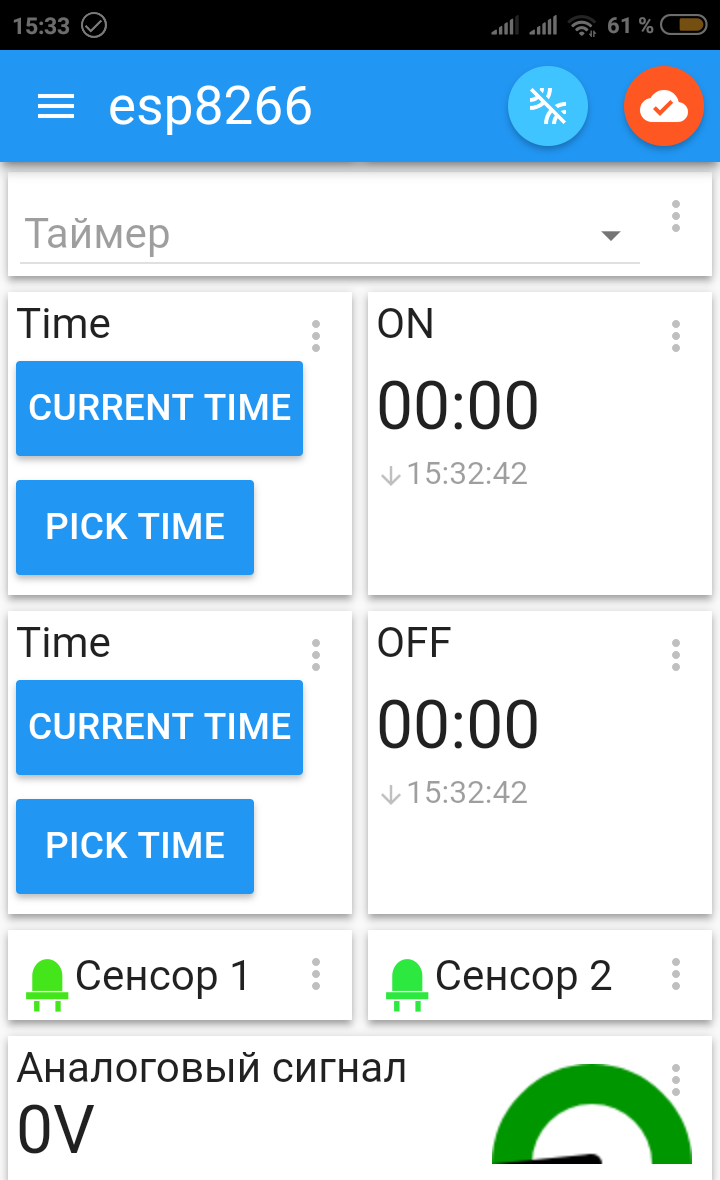
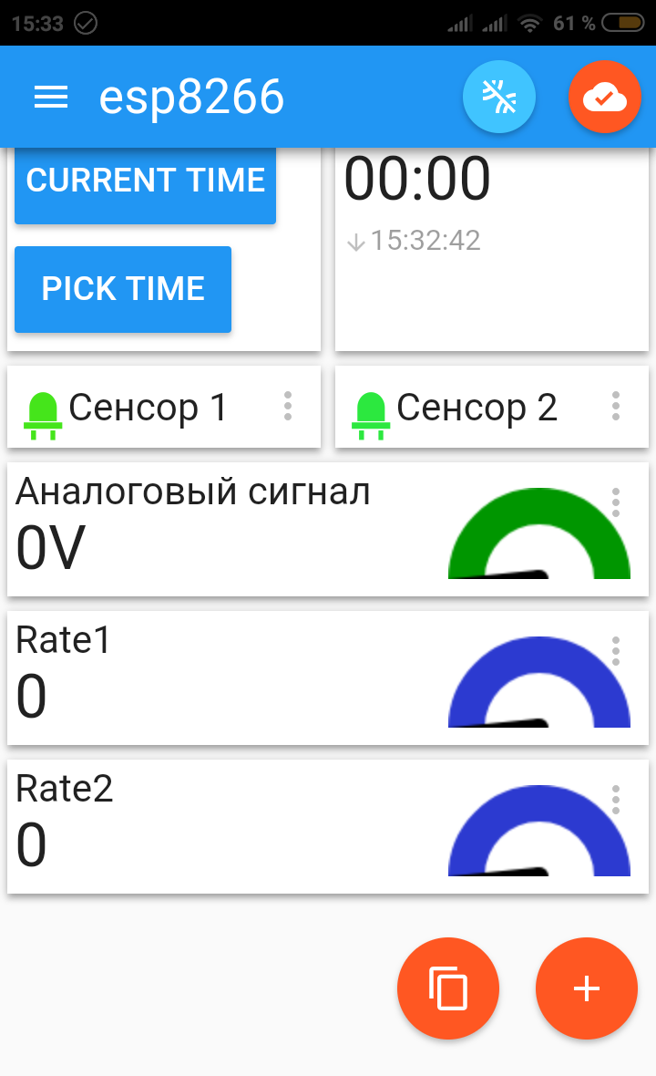
В качестве примера mqtt-панели было выбрано приложение: IoT MQTT Panel Пример реализации панели можно увидеть на скриншетах ниже.
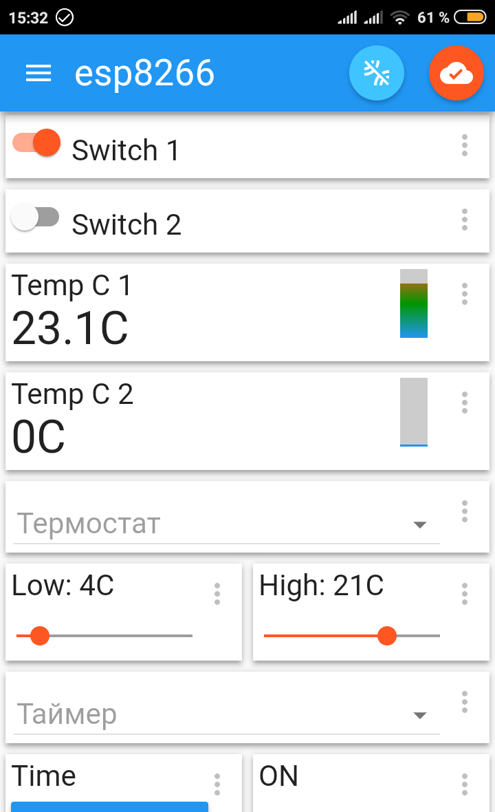
Потльзователь может настроить и разместить элементы по своему вкусу. Вы можете скачать файл для импорта настроек приложения с подготовленной панелью. Чтобы панель заработала с вашим устройством, нужно отредактировать файл перед импортом в приложении, заменить chip_id на цифры, которые вы сможете получить командой system, после того как загрузите программу в устройство и подключитесь к нему терминалом или по UART-у или по UDP протоколу (7777 порт).
Функции термостата и реле времени могут быть отключены, включены каждый на свое реле, например, первое реле времени управляет освещением, а второе реле термостата управляет двигателем отопления или включением газового котла. Если включить обе функции на одно реле, то будет работать следующая логика: в 1-ом режиме работы реле времени, термостат будет работать при включенном состоянии реле времени. Во 2-ом режиме реле времени термостат будет работать при выключенном реле времени.
Датчики температуры (DS18D20) настроены на работу с максимальной точностью (десятые доли градуса), эффективное значение усредняется 10-ю измерениями, что позволяет точно отслеживать изменение температуры.
Входные сенсоры ( 2 контакта ), работют по аппаратному прерыванию, которые можно использовать для подсчета импульсов на входе устройства с большой частотой. Данный функционал позволяет реализовать замеры различных расходов, например, воды, газа или электросчетчика. Информации о реализации датчиков расходов достаточно много. В настройках программы можно задать интервал в секундах для замера скорости импульсов и коэффициент пересчета для получения реальных значений скорости. Входы сенсоров могут быть логически связаны с выходами на реле, т.е. при логической единице на входе будет включено соответствующее реле. Например, подключив датчик движения, можно включать освещение, подключенное к одму из реле.
Реле времени
Реле времени может быть использовано для включения какой либо нагрузки в определенный промежуток времени. Для случая включения освещения в темное время суток предусмотрен 3-ий режим работы. Работа реле будет привязана к астрономическим часам, к моментам восхода и захода солнца. В момент восхода солнца реле будет отключаться, а в момент захода включаться. Необходимо будет задать географические координаты вашего местоположения и времени поправки в минутах относительно моментов восхода и заката. Точное время срабатывания реле будет рассчитываться: время восхода -(минус) время поправки и время заката +(плюс) время поправки. Так же можно задать и значения включения и выключения реле времени для режимов 1 или 2. Тогда результирующее состояние реле будет результатом двух условий по логической операции "И", т.е. реле времени будет в состоянии включено только в интервалы времени когда оно должно быть включено по астрономическому времени И в заданном временном интервале.
Термостат
Термостат имеет четыре режима работы. 1-ый и 2-ой режимы работают по алгоритму температурного гистерезиса. 1-ый режим работает на низком диапазоне температур (режим защиты от размораживания), а 2-ой режим на высоком (комфортном). Задаются температуры срабатывания термостата и интервал температурного гистерезиса, т.е. при срабатывании термостата он не отключит реле, пока не будет достигнута заданная температура +(плюс) интервал. Датчик температуры по которому работает термостат, выбирается в настройках устройства.
3-ий и 4-ый режимы работают по алгоритму PID контроллера (proportional–integral–derivative controller). 3-ий режим работает на низком диапазоне, 4-ый на высоком. Данный алгоритм обеспечивает более точное поддержание температуры в отличии от алгоритма температурного гистерезиса.
На картинке можно наблюдать эффект на различных значениях параметров PID алгоритма. По дефолту заданы следующие значения: Kp=2.0 Ki=5.0 Kd=1.0, длительность одного цикла выбрана 960 секунд (16 минут), ввиду большой инерционности систем отопления (значения настраивается). Параметры можно подбирать экспериментальным путем. Длительность рабочего цикла (включенного состояния реле) рассчитывается алгоритмом. В настройки вынесены минимальное время рабочего цикла, т.к. нет смысла включать двигатель отопления или газовый котел на слишком короткий интервал времени и максимальное время, выше которого реле будет постоянно включенным, опять же нет смысла отключать систему отопления на слишком короткое время.
Прошивка устройства NodeMCU
Устройство NodeMCU имеет встроенный адаптер USB-UART, поэтому вам потребуется лишь USB кабель от смартфона, скачать программу для компьютера esptool или Flash Download Tools (ESP8266 & ESP32), прочитать инструкцию по работе с ней и собственно запусть программу, которая загрузит файл во flash память устройства.
Затем подключиться программой terminal например вот этой
ScriptCommunicator / serial terminal к com порту
устройства на скорости 115200. Для настройки WiFi, введите команды:
ssid=ID_вашего_AP
password=пароль
поссле ввода ssid и пароля, устройство должно подключиться к вашей сети ...
не забудте ввести команду: commit, которая сохранит настройки в EEPROM-памяти.
Команда system выдаст нужный нам номер чипа - Chip ID.
PINs и их обозначения:
| Сенсор 1 | D6 |
| Сенсор 2 | D5 |
| Реле 1 | D2 |
| Реле 2 | D1 |
| Аналоговый вход ADC | A0 |
| Температурные датчики до 8-ми штук | D7 |
Прошивка устройства MP3509
Данное устройство не имеет встроенного адаптера UART-USB, поэтому вам потребуется его приобрести и впаять штырьки в качестве разъема на плату. UART разъем предусмотрен на плате устройства с пинами: 3,3V Tx Rx GND IO02 RST

1. Отключить основное питание 5 Вольт.
2. Соединить адаптер UART с устройством:
| 3,3V | 3,3V |
| Tx | Rx |
| Rx | Tx |
| GND | GND |
| IO02 | GND |
3. Подключить адаптер к USB порту и с помощью программы esptool загрузить программу в устройство. После чего цепь IO02 - GND нужно разорвать.
4. Можно приступить к настройке устройства через программу терминал.
PINs и их обозначения:
| Сенсор 1 | GPIO12 |
| Сенсор 2 | GPIO14 |
| Реле 1 | GPIO4 |
| Реле 2 | GPIO5 |
| Аналоговый вход ADC | ADC |
| Температурные датчики до 8-ми штук | GPIO13 |
| Не используется | GPIO02 |
Описание команд
Команды одинаково работают и через UART и через UDP протокол, посредством программы - терминал. Правая колонка - значения по default.
| ssid | ID вашей wi-fi сети. | WiFi-AP |
| password | Пароль вашей wi-fi сети. | 12345 |
| mqtt_host | Доменное имя mqtt сервера | mqtt.1vp.ru |
| mqtt_port | Номер порта mqtt сервера | 1883 |
| mqtt_login | логин пользователя для mqtt сервера | |
| mqtt_password | пароль пользователя для mqtt сервера | |
| udp_listen_port | номер UDP порта устройства | 7777 |
| udp_host_ip | IP адрес сервера(контроллера), который может принимать данные от устройства при их изменении в формате json | |
| udp_host_port | номер UDP порта сервера(контроллера) | 9777 |
| ow_scan | Поиск датчиков температуры на заданном выводе(PIN) устройства (esp8266), сразу после этой команды необходимо выполнить команду commit, чтобы сохранить адреса датчиков в энергонезависимой памяти устройства | 13 |
| ow_show | Отображение датчиков температуры, сохраненных в устройстве | |
| thermo_high_on | Температура срабатывания термостата в верхнем диапазоне | 21 |
| thermo_high_hyst | градусы температурного гистерезиса в верхнем диапазоне | 1 |
| thermo_low_on | Температура срабатывания термостата в нижнем диапазоне | 4 |
| thermo_low_hyst | градусы температурного гистерезиса в нижнем диапазоне | 4 |
| thermo_pid_time_cycle | Время цикла работы PID контроллера | 960 |
| thermo_pid_duty_cycle_min | Минимальное время рабочего цикла | 120 |
| thermo_pid_duty_cycle_max | Максимальное время рабочего цикла | 840 |
| thermo_pid_kp_ki_kd | Параметры PID алгоритма | 2.0, 5.0, 1.0 |
| thermo_sensor | номер сенсора для работы термостата | 1 |
| thermo_switch | номер реле для работы термостата | 2 |
| thermo_mode | режим работы термостата | 0 |
| pid | смотреть текущее параметры при работе PID алгоритма | |
| pid_restart | рестартовать PID алгоритм | |
| sensor1_to_switch1 | логическая связь для 1-го сенсора и 1-го реле | 0 |
| sensor2_to_switch2 | логическая связь для 1-го сенсора и 1-го реле | 0 |
| rate_interval | интервал времени в секундах для измерения скорости/частоты импульсов | 0 |
| rate_factor1 | коэффициент пересчета для получения реального значения скорости/частоты для сенсора 1 | 0.0 |
| rate_factor2 | коэффициент пересчета для получения реального значения скорости/частоты для сенсора 2 | 0.0 |
| adc_min | минимальное значение для измеряемой величины аналогово сигнала | 0.0 |
| adc_max | максимальное значение для измеряемой величины аналогово сигнала | 0.0 |
| time_switch | 1 | |
| time_switch_on | время включения реле времени в формате HH:MM | 00:00 |
| time_switch_off | время выключения реле времени в формате HH:MM | 00:00 |
| time_astro_location | Географические координаты | 0.0, 0.0 |
| time_astro_offset | Поправка времени срабатывания реле в режиме astro | 30 минут |
| time_mode | режим работы реле времени | 0 |
| timezone | временная зона | 5 |
| astro | вывод информации для режима astro | |
| ntp_server_one | ntp сервер 1 | pool.ntp.org |
| ntp_server_two | ntp сервер 2 | time.nist.gov |
| commit | сохранить все значения настроек в EEPROM устройства | |
| show | вывести все настройки устройства | |
| system | информация о системе: chip ID, MAC адрес, uptime - время непрерывной работы устройства после сброса дней:часов:минут:секунд | |
| time | текущее системное время | |
| reset | сброс устройства, почти как нажать кнопку reset | |
| getall | получить значения всех сенсоров в формате JSON | |
| get | получить значение конкретного PIN-а устройства ввода вывода GPIO | пример: get=4 |
| set | установить значение конкретного PIN-а устройства ввода вывода GPIO | пример: set=4=1 |
Описание topic-ов и их значений протокола mqtt
/1vp.ru/esp8266/chip_id - основной topic, в mqtt-панели занесен как префикс (prefix). chip_id - это номер чипа вашего устройства.
ниже описаны topic-и без префикса, все значения являются строковыми:
| / | switch1=0, switch1=1, switch2=0, switch2=1, sync - получить все значения | |
| /temp[1-8] | Цифровое значение с точкой | temp1 temp2 ... temp8 |
| /sensor1 | 0 или 1 | |
| /sensor2 | 0 или 1 | |
| /adc | Цифровое значение с точкой | |
| /counter1 | Цифровое значение | |
| /counter2 | Цифровое значение | |
| /rate1 | Цифровое значение с точкой | |
| /rate2 | Цифровое значение с точкой | |
| /time_on | время в формате HH:MM | |
| /time_off | время в формате HH:MM | |
| /time_mode | 0 - функция отключена, 1 - режим работы, 2 - режим работы, 3 - режим Astro | |
| /thermostat | 0 - функция отключена, 1 - режим работы в нижнем диапазоне, 2 - режим работы в верхнем диапазоне, 3 - режим PID конроллера в нижнем диапазоне, 4 - режим PID конроллера в верхнем диапазоне | |
| /thermostat_low | Цифровое значение | |
| /thermostat_high | Цифровое значение |
Замечания и предложения можно присылать на e-mail: info@1vp.ru
История измений
version: 0.3 (beta) 24.01.2019
- Обработка до 8-ми датчиков температуры DS18B20 на одной шине.
- Добавлен функционал реле времени - Astro.
version: 0.2 (beta) 14.01.2019
- Добавлен функционал термостата - PID контроллер.
version: 0.1 (beta) 17.12.2018
- Выпущена первая версия прошивки.