Thermostat and time relay based on esp8 2 6 6 chip
version: 0.3 (beta) 24.01.2019
This firmware is suitable for any device based on the esp8266 chip, as well as for universal devices based on this chip, for example, nodemcu. It should be borne in mind that the programmed functionality provides for a certain use of the output PINs of the esp8266 chip. Consider the operation of this firmware on the example of two boards NodeMCU v3 and MP3509 from MasterKit.
The main functions of the program are: thermostat, time relay, pulse counter or speed measurement (2 channels), load control (2 relays), temperature measurement
up to 8 sensors per channel through the 1-wire bus (all sensors are connected in parallel through a 4.7 kΩ resistor to the data pins and to the power supply of 5 volts,
the resistor is connected as close as possible to the device board, the length of the wire cannot be long,
because There is no 1-wire bus formation scheme on the device. See the description of the commands ow_scan and ow_show. )
and measurement of input voltage within 1 volt
(The measured voltage, for example, the battery charge level of 12 volts, must be submitted through a divider!)
Program allows you to enter the conversion factor and output already real values of the measured value.
The main functions are the functions of a thermostat and a time relay, usually they are implemented on the controller side.
But the esp8266 chip is powerful enough to put complex programs in the device’s internal memory and to refuse using controllers in simple automation cases.
Device management is carried out using MQTT and / or UDP protocols. The MQTT protocol allows the use of universal programs (mqtt-panels) for smartphones. UDP protocol can be used in the local network to communicate with the controller, for example, Openhab. If the mqtt protocol provides for a broker broker, via the UDP protocol, you can communicate with the device directly. Another goal, which was pursued during the implementation of this program - This is the autonomy of work, i.e. the device will work and perform basic functions even if the connection is lost, either with the mqtt broker or with the main controller.
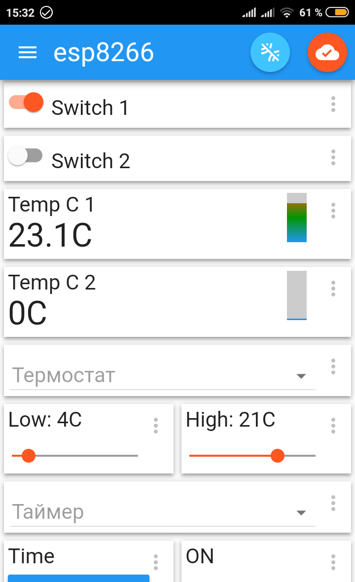
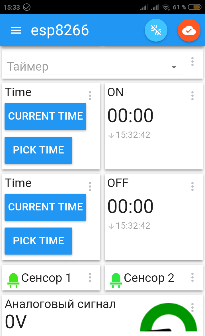
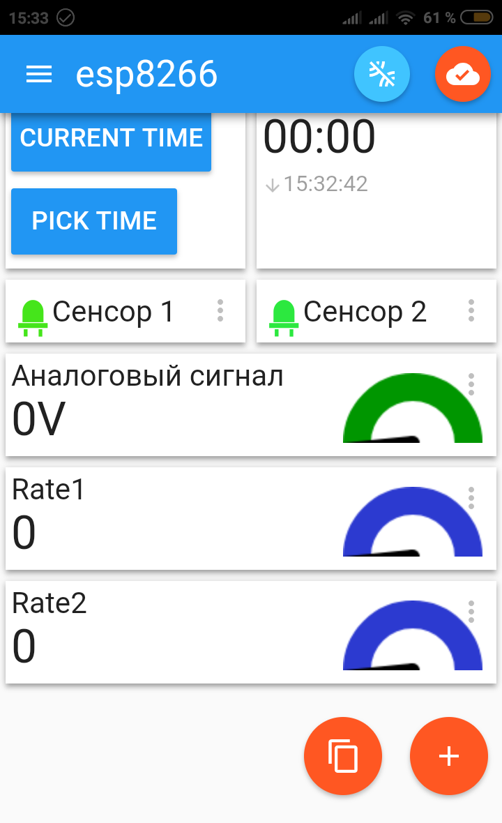
The following application was chosen as an example of the mqtt-panel: IoT MQTT Panel An example of the implementation of the panel can be seen in the screenshots below.


The user can customize and place the items to your liking. You can download the file for importing application settings with the prepared panel. To make the panel work with your device, you need to edit the file before importing it in the application, replace chip_id with numbers that you can receive with the system command, after you load the program into the device and connect to it with a terminal or via a UART or UDP protocol (port 7777).
The functions of the thermostat and the time relay can be turned off, each is switched on to its own relay, for example, the first time relay controls the lighting, and the second thermostat relay controls the engine heating or turning on the gas boiler. If you enable both functions on one relay, the following logic will work: in the 1st time switch operation mode, the thermostat will operate when the time switch is on. In the 2nd time relay mode, the thermostat will work when the time relay is off.
Temperature sensors (DS18D20) are configured to work with maximum accuracy (tenths of a degree), the effective value is averaged by 10 measurements, which allows you to accurately track temperature changes.
Input sensors (2 pins), work on a hardware interrupt, which can be used to count the pulses at the input of the device with a high frequency. This functionality allows to realize measurements of various expenses, for example, water, gas or an electric meter. Information about the implementation of cost sensors enough. In the program settings, you can set the interval in seconds for measuring the speed of the pulses and the conversion factor to obtain the actual speed values. Sensor inputs can be logically connected to relay outputs, i.e. for a logical unit, the corresponding relay will be turned on. For example, by connecting a motion sensor, you can turn on the lighting connected to one of the relays.
Time Relay
Time relay can be used to turn on any load in a certain period of time. For the case of turning on the lighting in the dark, a third mode of operation is provided. The relay will be tied to an astronomical clock, to the moments of sunrise and sunset. At the time of sunrise, the relay will turn off and turn on at sunset. It will be necessary to set geographical coordinates your location and correction time in minutes relative to sunrise and sunset. The exact time of the relay will be calculated: sunrise time - (minus) correction time and sunset time + (plus) correction time. It is also possible to set the on and off values of the time relay for modes 1 or 2. Then the resulting state of the relay will be the result of two conditions for the logical operation "AND", those. the time relay will only be able to turn on at intervals when it should be turned on at astronomical time AND in a given time interval.
Thermostat
The thermostat has four modes of operation. The 1st and 2nd modes work according to the temperature hysteresis algorithm. The 1st mode operates at a low temperature range (defrost protection mode), and the 2nd mode operates at a high (comfortable) level. The thermostat triggering temperatures and the temperature hysteresis interval are set, i.e. when the thermostat is triggered, it will not turn off the relay, until the target temperature + (plus) interval is reached. The temperature sensor on which the thermostat works is selected in the device settings.
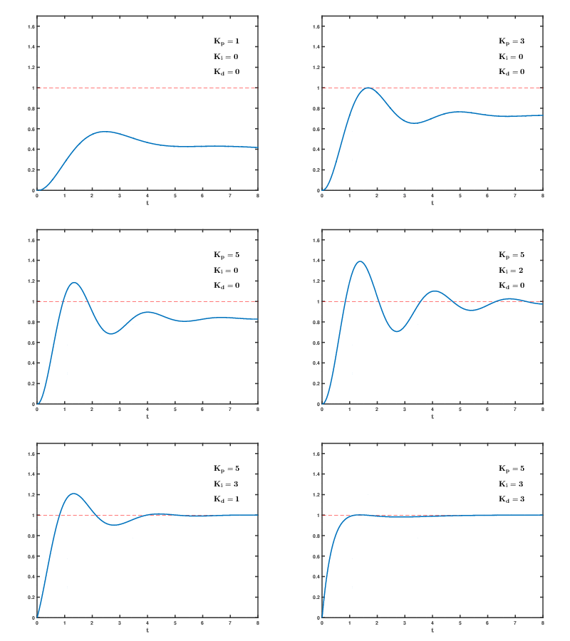
The 3rd and 4th modes work using the PID controller algorithm (proportional – integral – derivative controller). 3rd mode works on low range, 4th mode on high. This algorithm provides a more accurate temperature maintenance in contrast to the temperature hysteresis algorithm.

In the picture you can see the effect on different values of the parameters of the PID algorithm. The following values are set by default: Kp = 2.0 Ki = 5.0 Kd = 1.0, the duration of one cycle was chosen 960 seconds (16 minutes), due to the large inertia of the heating systems (values are adjustable). Parameters can be selected experimentally. The duration of the operating cycle (on state of the relay) is calculated by the algorithm. The settings made the minimum time of the working cycle, because it makes no sense to turn on the engine heating or gas boiler on too a short time interval and the maximum time beyond which the relay will be permanently on, again, there is no sense in switching off heating system for too short a time.
Programming NodeMCU
The NodeMCU device has a built-in USB-UART adapter, so you only need a USB cable from a smartphone, download the program for the computer esptool or Flash Download Tools (ESP8266 & ESP32) , read the instructions for working with it and run the program itself, which will load the file into the flash memory of the device.
Then connect with terminal for example this
ScriptCommunicator / serial terminal to the com port
devices at a speed of 115200. To configure WiFi, enter the commands:
ssid = your_ap_ap
password = password
After entering the ssid and password, the device should connect to your network ...
do not forget to enter the command: commit, which will save the settings in the EEPROM memory.
The system command will give us the chip number we need - Chip ID.
PINs definition:
| Sensor 1 | D6 |
| Sensor 2 | D5 |
| Relay 1 | D2 |
| Relay 2 | D1 |
| Analog input ADC | A0 |
| Temperature sensors up to 8 units | D7 |
Programming MP3509
This device does not have a built-in UART-USB adapter, so you will need to purchase it and solder the pins as a connector to the board. A UART connector is provided on the pinboard device: 3.3V Tx Rx GND IO02 RST

1. Disconnect main power 5 volts.
2. Connect the UART adapter to the device:
| 3,3V | 3,3V |
| Tx | Rx |
| Rx | Tx |
| GND | GND |
| IO02 | GND |
3. Connect the adapter to the USB port and use the esptool program to load the program into the device. After that, the chain IO02 - GND must be broken.
4. You can proceed to configure the device through the terminal program.
PINs definition:
| Sensor 1 | GPIO12 |
| Sensor 2 | GPIO14 |
| Relay 1 | GPIO4 |
| Relay 2 | GPIO5 |
| Analog input ADC | ADC |
| Temperature sensors up to 8 units | GPIO13 |
| Not used | GPIO02 |
Commands
Commands work the same way through UART and UDP protocol, through the program - terminal. Right column - default values.
| ssid | ID your wi-fi net. | WiFi-AP |
| password | Password of the wi-fi net. | 12345 |
| mqtt_host | Domain name of a mqtt server | mqtt.1vp.ru |
| mqtt_port | Post number of a mqtt server | 1883 |
| mqtt_login | login for a mqtt server | |
| mqtt_password | password for a mqtt server | |
| udp_listen_port | UDP port number of the device | 7777 |
| udp_host_ip | IP address of a controller(server), which can receive data from the device when it changes in json format | |
| udp_host_port | UDP port number of a controller(server) | 9777 |
| ow_scan | Search for temperature sensors on a given pin (PIN) device (esp8266), immediately after this command, you must execute the commit command to save the addresses of the sensors in the non-volatile memory of the device | 13 |
| ow_show | Display of temperature sensors stored in the device | |
| thermo_high_on | Thermostat trigger temperature in the upper range | 21 |
| thermo_high_hyst | degrees hysteresis in the upper range | 1 |
| thermo_low_on | The temperature of the thermostat in the lower range | 4 |
| thermo_low_hyst | degrees of temperature hysteresis in the lower range | 4 |
| thermo_pid_time_cycle | PID controller cycle time | 960 |
| thermo_pid_duty_cycle_min | Minimum duty cycle time | 120 |
| thermo_pid_duty_cycle_max | Maximum duty cycle time | 840 |
| thermo_pid_kp_ki_kd | PID algorithm parameters | 2.0, 5.0, 1.0 |
| thermo_sensor | sensor number for thermostat operation | 1 |
| thermo_switch | relay number for thermostat operation | 2 |
| thermo_mode | thermostat mode | 0 |
| pid | view current parameters when running PID algorithm | |
| pid_restart | restart PID algorithm | |
| sensor1_to_switch1 | logical connection for the 1st sensor and the 1st relay | 0 |
| sensor2_to_switch2 | logical connection for the 2st sensor and the 2st relay | 0 |
| rate_interval | time interval in seconds to measure the speed / frequency of the pulses | 0 |
| rate_factor1 | conversion factor for obtaining the actual speed / frequency for sensor 1 | 0.0 |
| rate_factor2 | conversion factor for obtaining the actual speed / frequency for sensor 2 | 0.0 |
| adc_min | minimum value for measured value analog signal | 0.0 |
| adc_max | maximum value for measured value analog signal | 0.0 |
| time_switch | Time relay switch number | 1 |
| time_switch_on | time of switching ON of time relay in HH:MM format | 00:00 |
| time_switch_off | time OFF timer in format HH:MM | 00:00 |
| time_astro_location | Geographical coordinates | 0.0, 0.0 |
| time_astro_offset | Astro relay time correction | 30 minutes |
| time_mode | timer operation mode | 0 |
| timezone | time zone | 5 |
| astro | output information for astro mode | |
| ntp_server_one | ntp server 1 | pool.ntp.org |
| ntp_server_two | ntp server 2 | time.nist.gov |
| commit | save all setting values to device eeprom | |
| show | display all device settings | |
| system | system information: chip ID, MAC address, uptime - time of continuous operation of the device after resetting the days: hours: minutes: seconds | |
| time | current system time | |
| reset | reset the device, almost like pressing the reset button | |
| getall | get the values of all sensors in json format | |
| get | get the value of a specific pin input device output GPIO | example: get=4 |
| set | set the value of a specific pin of a GPIO input output device | example: set=4=1 |
MQTT topics
/1vp.ru/esp8266/chip_id - The main topic, in the mqtt-panel is listed as a prefix. chip_id is the chip number of your device.
The following describes the topic without a prefix, all values are string:
| / | switch1=0, switch1=1, switch2=0, switch2=1, sync - get all values | |
| /temp[1-8] | Digital value with a dot | temp1 temp2 ... temp8 |
| /sensor1 | 0 or 1 | |
| /sensor2 | 0 or 1 | |
| /adc | Digital value with a dot | |
| /counter1 | Digital value | |
| /counter2 | Digital value | |
| /rate1 | Digital value with a dot | |
| /rate2 | Digital value with a dot | |
| /time_on | time in HH:MM format | |
| /time_off | time in HH:MM format | |
| /time_mode | 0 - the function is disabled, 1 - operation mode, 2 - operation mode, 3 - Astro mode | |
| /thermostat | 0 - the function is disabled, 1 - the operating mode in the lower range, 2 - the operating mode in the upper range, 3 - the PID mode of the controller in the lower range, 4 - the PID mode of the controller in the upper range | |
| /thermostat_low | Digital value | |
| /thermostat_high | Digital value |
Comments and suggestions can be sent to the e-mail: info@1vp.ru
Change log
version: 0.3 (beta) 24.01.2019
- Processing up to 8 temperature sensors DS18B20 on one bus.
- Added time relay functionality - Astro.
version: 0.2 (beta) 14.01.2019
- Thermostat functionality added - PID controller.
version: 0.1 (beta) 17.12.2018
- First firmware released.